The featured image of this blog post has been generated by Stable Diffusion.
What does it take to build a geocaching box that can only be opened at sunset? A box, a button, an electronic lock, an electronic clock, and a controller that ties everything together.
Motivation
For some years, I owned a geocache that could only be found at sunrise. You had to look out for a Bluetooth transmitter, which was only active around sunrise. The Bluetooth device name of the transmitter contained the final coordinates. In October 2021, somebody stole the solar-powered Bluetooth transmitter, and for this reason, I had to archive this particular cache.
So, should I come up with a sequel? Since geocachers considered it quite demanding to be up at sunrise, I contemplated a geocache that you only could find around sunset. Then somebody pointed out a particular way to build an electronic lock with an RC servo and some 3D-printed parts. Did I mention that recently I became the proud owner of a 3D printer? At that point, the project started.
Electronic locks
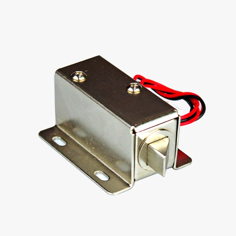 Solenoid locks, as shown in the left picture, need 12 V and 1-2 A, which is not what you want to put into a small treasure box. An alternative is to build locks that are controlled by RC servos.
 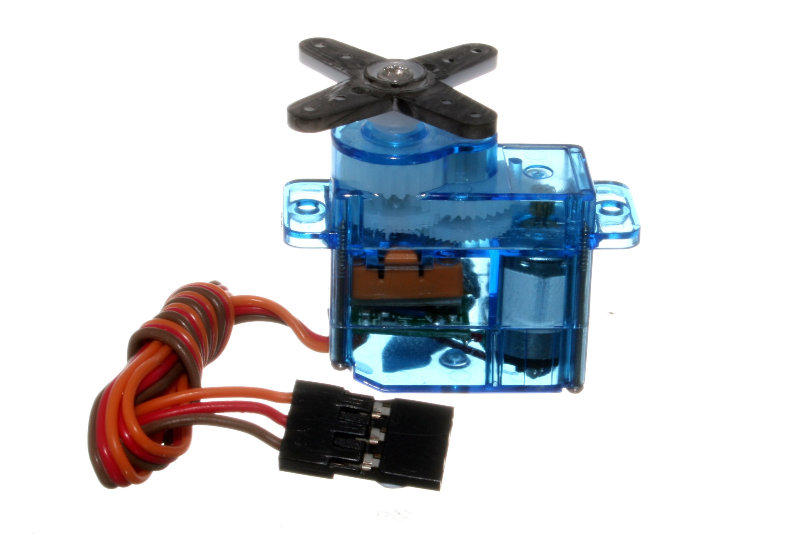 The advantage is that servos (see right picture) operate at 4-6 V and usually draw 200-300 mA maximum. However, a servo motor by itself is not a lock, and you have to come up with a locking mechanism. Most of these use a deadbolt mechanism, e.g., the one used in the reverse geocache box by Mikal Hart.
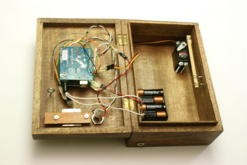
While such a lock is good enough if you want to open the box once, you run into a problem when the box should be locked and unlocked a couple of times. One needs to know the position of the lid in order to engage the lock, which makes the hole construction somewhat brittle.
As mentioned, somebody pointed me to a 3D-printed latch mechanism, which looks very convincing.
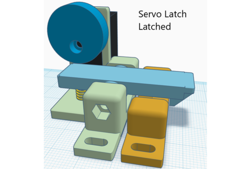
The good point about this mechanism is that one can close the lock when the latch is in the latched position. Of course, I had to try this out immediately.
A couple of hours later, the latch was printed and attached to the inside of a box. In addition, a spring opens the lid, when the latch is in the unlatched position. The only necessary adaptation that was necessary was to scale the cam down to 97% so that it fit on the RC servo axis.
Electronic components
Having the lock in place, what else do we need? As pointed out above, we need additionally a clock and a controller. I picked the ATtiny1634 as the MCU, because I still have a lot of them in my spare part box, because it has more flash memory than most of the other classic ATtinys, and because it is energy efficient.
For the real-time clock, I chose the RV8803 by Micro Crystal, which is quite an impressive RTC. It guarantees 3 ppm over the entire temperature range of -40 to +85 °C, it allows for adjusting the age offset, and it draws only 240 nA. Sparkfun has a breakout board with this chip, which is much more costly than the cheap DS3231 boards. However, one gets guaranteed quality instead of questionable chips, which often seem to work outside their specifications.
Since I own the frequency counter FA-2 by BG7TBL, I was able to adjust the RTCs age offset.
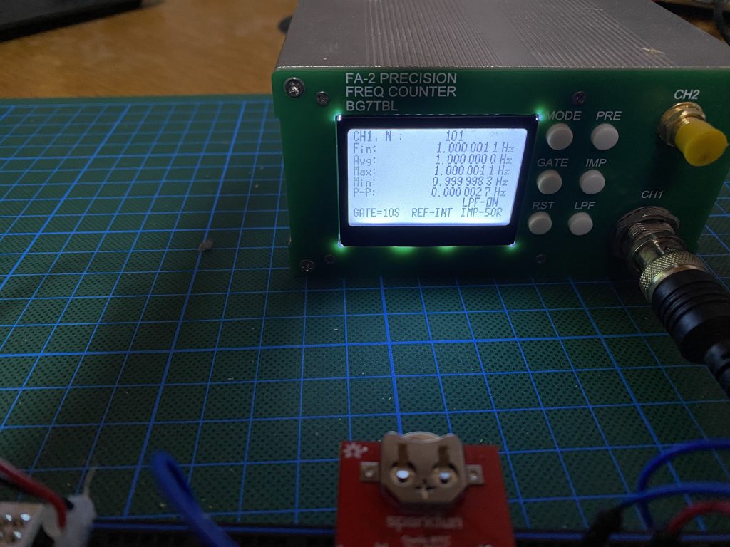
I now have a short-term accuracy for the 1 Hz clock signal of less than 0.1 ppm, as the frequency counter shows after 100 measurements of 10-second intervals. Awesome! I will nevertheless assume a possible deviation of 3ppm, meaning that the acceptance interval of the box grows over time by ±2 seconds per week.
In addition to the MCU and the RTC, I threw in an MP3 module for good measure. I used the FN605-M1, of which I have a few in my spare part box, but which are not produced anymore. It will give a short rejection message when somebody tries to open the box at inappropriate times, and it will give a wordy greeting when the geocacher has opened the box at sunset. The MP3 module and the RC servo are each switched using a P-channel logic level FET (IRML6402) as a high-side switch, which only supplies power when needed – which completes the ingredient list.
Software
The software is sort of straightforward. Most of the time, the MCU is in power-down mode and wakes up only when the button is pressed. In this case, the MCU needs to check whether we have reached sunset. If so, the box opens, and the voice module will entertain the successful geocacher. Otherwise, the red LED lights up, and some voice tells the geocacher that it is not the right time. If the geocacher pushes the button too often, the box will become silent (in order to save battery power).
Computing the sunset time is therefore the most important task. There are Arduino libraries out there, which can compute sunset times for you. Or you program the equation of time from scratch. Regardless of what of the two options you choose, you end up with quite a chunk of flash memory used up by this part of the program because a number of floating point math libraries have to be imported. Because the box already needed several libraries, and since I wanted to have some code that implements logging, hardware monitoring, maintenance functions, and some secret backdoor, I had to reduce this.
So, I wrote a C program that generated on a Mac the sunset times for all days of the year at the point where the cache box will be hidden, which I then put into a PROGMEM array. This led to a reduction of roughly 3 KB of flash memory.
All in all, in the end, the program code used up almost all of the flash memory of 16 KB.
Power demands & battery lifetime
One critical question is, of course, what kind of battery one should use. As mentioned elsewhere, my favorite batteries are 3.6-volt Li-SOCI2 AA cells. In this case, however, they are not good enough. These batteries are very long-lasting and have a high capacity, but they do not deal well with impulse currents of a few hundred mA. For this reason, I decided to use three 1.5-volt Lithium AA cells, which have a capacity of 3000 mAh. Their initial open-circuit voltage can be as high as 1.8 V. In other words, the initial voltage can be 5.4 V, which is just inside the specifications of the MCU and RTC. After a few minutes of usage, the batteries have an open circuit voltage of roughly 1.6 V, which drops below 1.5 V only when the battery is almost empty. When there is a considerable load (around 200-300 mA), the voltage can be 0.3-0.4 V lower. However, 3.6 V is still enough to operate the servo and to drive the MP3 module. This all implies that we can get away without any voltage regulator and the quiescent current will be dominated by the power-down current of the MCU and the RTC, which in sum is less than 0.5 µA (see picture below). Assuming a self-discharge rate of 1%/year or less for the Lithium batteries, this is considerably less than the equivalent average self-discharge current of 3.4 µA.
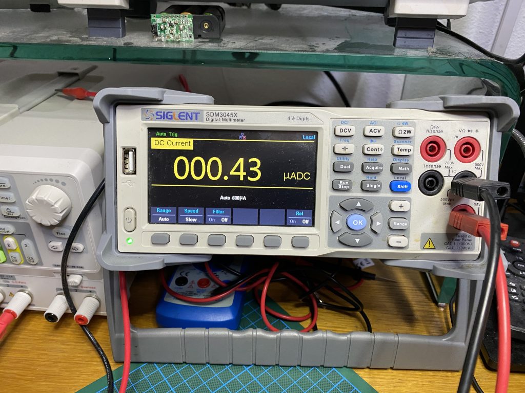
This way, after 10 years, the cache box will have burned 340 mAh by doing nothing. Assuming that we can use the batteries up to 2500 mAh, this leaves us 2160 mAh for visits by geocachers.
Calculating the power for each visit is more difficult because the RC servo and the MP3 module have highly fluctuating power demands. A very crude approximation for each successful visit could be done as follows. The servo may be active for 5 seconds at, say, 200 mA. In addition, the MP3 module uses 200 mA for 1 minute, which in sum is equivalent to 3.6 mAh. There is a more accurate way to determine the needed charge, though. You could use a coulomb counter.
Incidentally, I own an LTC4150 breakout board, which can be used to count coulombs. Hooking that up to the prototype revealed that one visit uses roughly 2.0 mAh (instead of 3.6 mAh as estimated earlier). This means, 1080 visits should be possible. An unsuccessful visit could use up to 0.17 mAh. Expecting unsuccessful visits and trying to stay on the safe side, one should probably change batteries after 600 successful visits or 10 years, whatever happens earlier.
The prototype box
After having developed the electronics on a breadboard and written the software, the final part is to put everything in a box. I started with a prototype, as shown in the next picture.
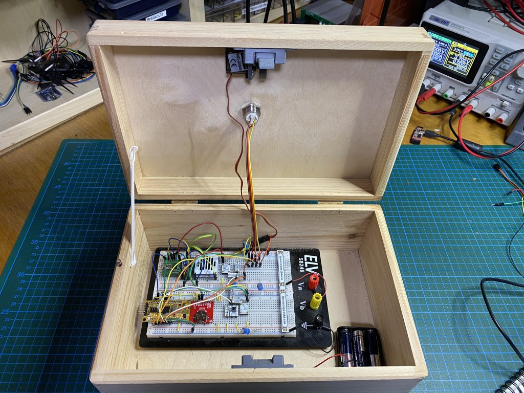
This prototype is already fully operational, as can be seen in the following video, which has been recorded around the time of sunset (simulated in the RTC).
Some final polishing is clearly needed. A printed circuit board needs to be designed, and the box should be smaller and nicer. I also printed the latch mechanism again, this time using PETG, which is more robust than PLA.
The final box
After having designed the PCB and sending the design data off to a PCB fab, the printed circuit boards arrived only a few days later. Soldering all the components to the board, a first test of the functionality showed that everything worked as expected. This time, I even did not need an additional wire!
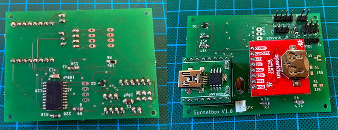
Now this has to be mounted in a nice box. And I also designed a cover for the electronics, which also acts as a front for the loudspeaker. Actually, this is the first 3D-printed thing I designed. For the records, I used Tinkercad to do that, and it was quite manageable for somebody not having worked on 3D design before.
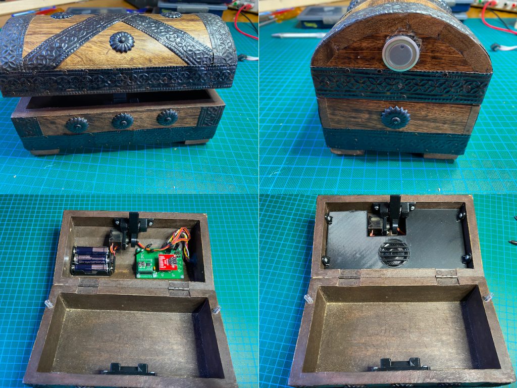
Well, in the end, there was a small problem. The frame for the RC servo, which I glued to the lock mechanism, came off. The glue I used, E6000 Plus, is obviously good for PLA, but not for PETG. After some googling, I ordered Top2Glue medium, which seems to be up for the job.
All in all, I am impressed with what you can do with 3D printing. From having the idea of using the lock mechanism to the completed design of the final box, it took only three weeks, including a couple of days to wait for the PCB, missing tools or glue. And now I hope that geocachers will enjoy the box when they find it.

Leave a Reply